- Date: 2002 – 2003.
- Owner company: CreaSoft SL.
- Developed by CreaSoft SL.
- Clients: Valeo.
- Authors: Raúl Bartolomé Castro and other engineers.
- Contribution of Raúl: electronic engineer. Design of PCBAs, including schematics, layout, selection of components and hardware validation. C software development for microcontrollers.
- Market: electrical wiring.
- Product category: electrical test.
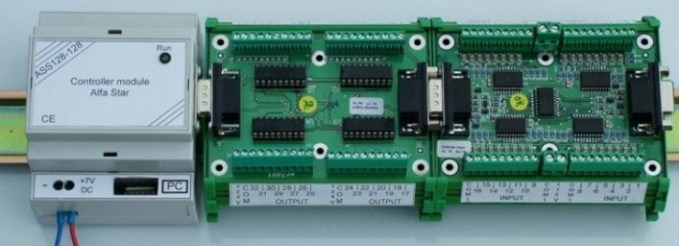
The purpose of the project is to check the wiring harness, this time the mechanical enclosure is not a rack, but cards located on plastic guides, thus providing greater versatility. In the following photograph we can see an example of different cards located in the guides and interconnected with each other.

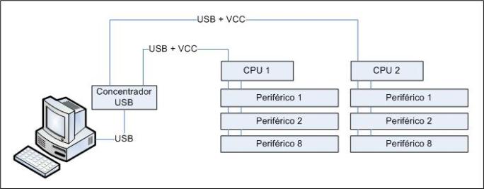
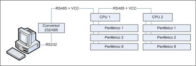
These systems consist of electronic cards controlled by the PC. Communication with this is done through the USB bus if there are high transmission speed requirements, or through the RS485 bus if long distances are desired in industrial environments. The general diagrams of these systems are presented below.
The following illustration shows how the PC communicates with a USB hub (HUB), and this in turn does so with each CPU card. In total, a star topology network of up to 127 nodes can be implemented (typical of a USB network). Each CPU card can control up to 8 peripherals.

In this other image, the PC communicates with a card that converts from RS232 to RS485, then through a bus connection topology each CPU card is connected. The total network is determined by the speed requirements, but up to 127 nodes can be reached.

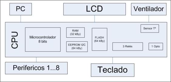
The CPU node is characterized by its versatility and power at a reasonable price. Depending on the application, there is a variant of the circuit or another, in this way the economic resources are optimized. The following illustration presents the full version.

The CPU is designed around an 8-bit microcontroller (Cypress in the case of the USB model and AVR from Atmel if it is the model require RS485) and a PLD (from Altera or Lattice respectively). Regarding the memory external to the microcontroller, a SRAM memory of 32 KBy (data), an EEPROM memory of up to 64 kBy maximum (non-volatile data), a FLASH memory of 64 kBy (program) have been implemented. As internal peripherals there is an I2C temperature sensor, 3 electromechanical relays and an opto-coupled input.
The external peripherals are: a 2-row 40-character LCD display to present information to the user, an 8-key keyboard for data acquisition by the user, and a fan to expel heat if necessary. Obviously, up to eight peripheral cards can still be connected as shown in the general diagram.
The peripheral cards developed have been two. The first consists of 64 inputs for detection of potential-free contacts. The second has 64 inputs for contact detection plus 64 outputs for activation of light emitting diodes (LEDs). In total each CPU card can address 128 bytes.
This system can work in two ways. As shown in the first two illustrations, that is, fully controllable by the PC. It can also work autonomously (stand alone), where the PC does not intervene, as much to update data or other activities.


